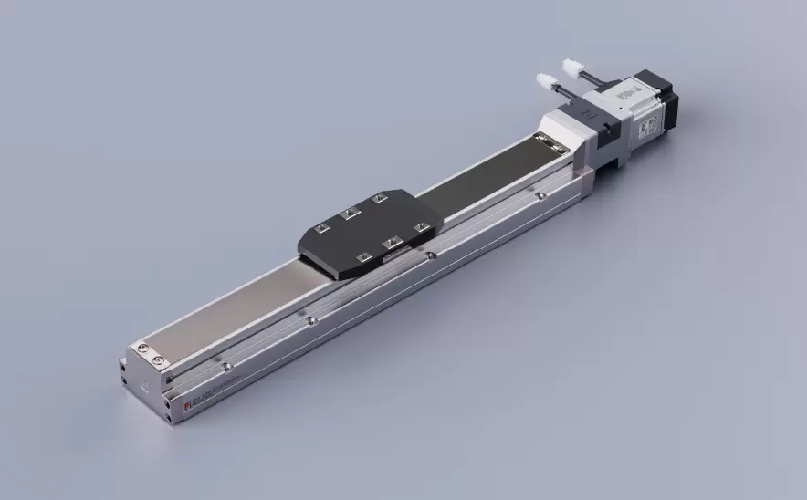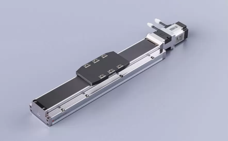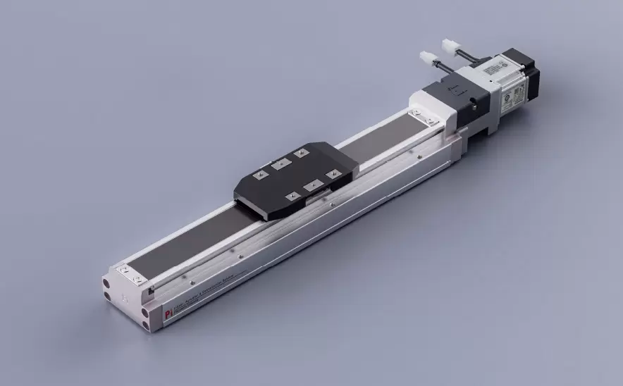
Motor Bottom Side
Repeatability:±0.005/0.01mmHorizontal Load:150kgVertical Load:55kgMaximum Speed:2000mm/sTravel Range:100-1500mm
 Current location:Home > Company > News > Latest news > precision positioning slide table Purchase Guide: How to Match Models According to Load Requirements
 Date: Jan 07 2026
precision positioning slide table, as a core component in fields such as automation equipment, precision measurement, and semiconductor manufacturing, its performance directly affects the positioning accuracy and stability of the equipment. Load matching is the primary prerequisite for selection - if the slide table's load-bearing capacity is insufficient or the redundancy is too large, it may lead to a decrease in accuracy, a shortened service life, or even equipment failure. Conversely, it will lead to cost waste. This article will systematically explain how to precisely match the model of the slide table according to the load requirements from four aspects: load characteristic analysis, interpretation of key parameters of the slide table, selection logic and precautions.
I. Clarify Load Characteristics: The "Starting Point" for Selection
Load is not merely a "weight value", but a comprehensive parameter determined by static load, dynamic load, center of gravity distribution, direction of motion, and other factors. The following key information needs to be quantified first:
1. Load type and size
Static load: The weight that the slide table bears when it is stationary (including workpieces, fixtures, etc.), with units of N or kg (1kg≈9.8N).
Dynamic load: The dynamic force that the slide table bears during movement (acceleration/deceleration), which needs to be calculated in combination with the movement speed and acceleration (formula: F = ma + mg, where m is the total mass, a is the acceleration, and g is the acceleration due to gravity).
If the load mass is 10kg and it is accelerated at 0.5m/s², the dynamic load is 10×(0.5+9.8)=10 ³ N (approximately 10.5kgf). If placed only statically, it is 98N (10kgf).
2. Position of the load center of gravity
• Central load: The center of mass of the load coincides with the movement axis of the slide table (ideal state), at which point the slide table is subjected to uniform force and undergoes minimal deformation.
• Eccentric load: When the center of mass deviates from the moving axis (such as in a single-sided cantilever installation), an overturning moment will be generated (M = F×d, where F is the load force and d is the eccentricity). For instance, with a 10kg load eccentricity of 50mm, the overturning moment is 98N×0.05m=4.9N·m, which may exceed the bending resistance capacity of the slide table.
3. Direction of motion and load direction
The slide table usually moves in a straight line (X/Y/Z axis), and it is necessary to clarify whether the load is in the vertical direction (greatly affected by gravity) or the horizontal direction (mainly affected by inertial force). For instance, a vertically installed Z-axis slide table needs to simultaneously bear the self-weight of the load (static load) and the inertial force during movement (dynamic load), thus having a higher requirement for rigidity.
4. Load nature
• Rigid loads (such as metal blocks) : Small deformation, mainly affecting the rigidity of the slide table;
• Flexible loads (such as elastic fixtures) : Vibration may occur, so the slide table needs to have damping characteristics;
• Impact load (such as rapid start and stop) : The impact resistance capacity of the slide table needs to be considered (usually the manufacturer will indicate the "maximum instantaneous load").
Ii. Key Parameters of the Slide Table: The "Ruler" of Load-bearing Capacity
The load-bearing capacity of the slide table is determined by its structural design and materials. The following parameters need to be given special attention:
Rated Load
• Definition: The "safe working load" marked by the manufacturer is divided into static rated load (the maximum allowable load when stationary) and dynamic rated load (the maximum allowable load when in motion).
Note: The dynamic rated load is usually lower than the static rated load (due to inertial force during movement), and it is necessary to distinguish between "horizontal installation" and "vertical installation" (when installed vertically, the load includes gravity, and the rated value is lower).
For example, a certain slide table is marked with "static rated load 50kg, dynamic rated load 20kg (horizontal)", indicating that the maximum load during horizontal movement is 20kg and it can carry 50kg when stationary.
2. Stiffness
• Definition: The ability to resist deformation, typically measured in N/μm (the force required for deformation per micrometer). The higher the rigidity, the smaller the deformation under load and the more stable the positioning accuracy.
• Influencing factors: Guide rail type (ball guide rail > sliding guide rail > crossed roller guide rail?) It depends on the specific design, the material of the main body (cast iron > aluminum alloy > engineering plastic), and the cross-sectional dimensions.
• Load correlation: Eccentric loads or large loads can significantly reduce system rigidity (for example, the rigidity at both ends of a long-stroke slide is weaker than that in the middle), and this needs to be verified through the "load-rigidity curve" (provided by some manufacturers).
3. Compatibility of guide rail type with load
The load-bearing characteristics and applicable scenarios of different guide rail structures vary significantly:
Characteristics of guide rail types, load adaptability, typical applications
Ball guide rail rolling friction, low friction, high precision, medium rigidity, medium and small load (≤100kg), suitable for high-speed, low-vibration scenarios 3C inspection and small automated equipment
The rollers of the crossed roller guide rail are arranged orthogonally, featuring high rigidity and high precision. It has a strong load-bearing capacity for medium loads (50-500kg) and a strong ability to resist overturning moments. It is suitable for semiconductor wafer handling and precision machine tools
The sliding guide rail has sliding friction, a simple structure, low cost, and high rigidity for large loads (≥500kg), but it is prone to crawling at low speeds in heavy machinery and low-speed positioning scenarios
Air float/magnetic float guide rails have no contact support, zero friction, and ultra-high rigidity and ultra-precision scenarios (load usually ≤50kg) for photolithography machines and nanometer-level positioning platforms
4. The drive mode matches the load
The drive mode of the slide table (lead screw, linear motor, synchronous belt, etc.) will affect the load transmission efficiency and dynamic performance
• Ball screw drive: It is transmitted through the lead screw nut, and the load is borne by the lead screw. The "axial load capacity" of the lead screw (related to lead and rotational speed) needs to be checked.
• Linear motor drive: No intermediate transmission, directly pushes and pulls the load, suitable for scenarios with large loads and high acceleration (but requires strong rigid guide rails);
• Synchronous belt drive: It is transmitted by friction, and the load should not be too large (prone to slipping). It is suitable for light load (≤20kg) and high-speed scenarios.
Iii. Selection Logic: From Load Requirements to model matching
Based on the above analysis, the following steps can be followed for precise selection:
Step 1: Calculate the total load and dynamic force
• Total mass m_{total} = m_{load} + m_{slide table body} + m_{fixture} (the mass of the slide table body should be checked in the manufacturer's manual);
• Dynamic load F_{dynamic} = m_{total}×a (a is the maximum acceleration, usually taken as 0.3-0.5m/s², and can reach 1-2m/s² in high-speed scenarios);
For eccentric loads, the overturning moment M = F_{total}×d needs to be calculated to ensure that the "maximum allowable overturning moment" marked on the slide table is ≥M.
Step 2: Determine the safety factor
In precision applications, the safety factor is usually taken as 1.5 to 2 times (i.e., actual load ≤ rated load/safety factor) to cope with sudden overloads or long-term wear. For example, if the calculated dynamic load is 30kg and a safety factor of 1.5 is selected, then the dynamic rated load of the slide table should be ≥45kg.
Step 3: Match rigid demands
When the positioning accuracy requirement is ±1μm, a slide table with a rigidity of ≥500N/μm should be selected (insufficient rigidity will lead to "load-deformation" error).
In eccentric load scenarios, crossed roller guides or double-guide structures are preferred (to enhance anti-overturning capacity).
Step 4: Verify installation compatibility with the environment
• Installation space: The size (width, height) of the slide table should be compatible with the equipment space. For long-stroke slide tables, the "cantilever effect" (excessive length can lead to a decrease in rigidity) should be taken into consideration.
• Environmental protection: For dust and oil contamination scenarios, select a protection grade of IP54 or above. For high-temperature scenarios, confirm the temperature resistance of the slide table material (e.g., aluminum alloy ≤120℃, cast iron ≤200℃).
• Service life requirement: Based on the average daily operating time, verify the "rated service life" of the slide table (usually expressed as "operating distance", for example, L10 service life =50km).
Iv. Common Misunderstandings and Precautions
Confusing "static load" with "dynamic load" : Ignoring the inertial force during movement can cause the slide table to overload, overheat or drift in accuracy (for example, a slide table with a static rating of 50kg May be damaged if the dynamic load exceeds 20kg).
2. Ignoring center of gravity offset: A 10kg load with an eccentricity of 50mm is equivalent to an increase in the center load to 15kg (this needs to be verified in combination with the bending stiffness of the slide table).
3. Excessive pursuit of high precision: High-rigidity slides are costly and heavy. If the load only requires ±10μm accuracy, ordinary ball guides can be selected (to avoid performance redundancy).
4. Ignore the manufacturer's test conditions: Some manufacturers indicate that the "rated load" is the data under low speed (≤0.1m/s) and short stroke. In high-speed scenarios, it needs to be derated (refer to the "speed-load curve").
V. Typical Scenario Selection Examples
Key parameters of the recommended slide type for scene load characteristics
Semiconductor wafer inspection (X-axis) load 5kg (wafer + suction cup), eccentricity ≤10mm, accuracy ±1μm. Cross roller guide + ball screw drive rated load ≥10kg, rigidity ≥800N/μm, repeat positioning accuracy ±0.5μm
3C product assembly (Z-axis) load 2kg (fixture + parts), vertical installation, frequent start and stop ball guide + servo motor drive, vertical rated load ≥5kg, dynamic rated load ≥3kg, protection grade IP54
Heavy machinery positioning (Y-axis) load 200kg, horizontally installed, low-speed (≤0.2m/s) sliding guide + rack and pinion drive, static rated load ≥300kg, rigidity ≥300N/μm
Summary
The load matching of the precision positioning slide table requires "quantification of requirements + benchmarking parameters" : First, clarify the mass, center of gravity, and motion state of the load, and then combine the core parameters such as the rated load, rigidity, and guide rail type of the slide table, and verify the adaptability through safety factors and dynamic checks. Avoid blindly pursuing "high-end configuration". Only by aiming for "meeting precision requirements, ensuring lifespan and controlling costs" can the most optimal type be achieved.