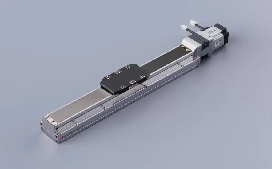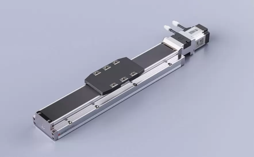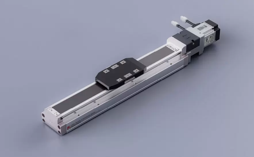
Motor Bottom Side
Repeatability:±0.005/0.01mmHorizontal Load:150kgVertical Load:55kgMaximum Speed:2000mm/sTravel Range:100-1500mm
 Current location:Home > Company > News > Latest news > precision positioning slide table Regular calibration process: Application steps of Laser interferometer
 Date: Jan 21 2026
The positioning accuracy (±0.1μm to ±10μm), repeat positioning accuracy and motion straightness of the precision positioning slide table will deteriorate over time due to mechanical wear, thermal deformation or loose assembly. Regular calibration is the core means to ensure the performance of the equipment. Laser interferometers, with their nanoscale measurement accuracy (up to 0.1μm) and non-contact measurement advantages, have become the "gold standard" for slide table calibration. This article elaborates on the standardized application steps of laser interferometers in slide table calibration from five aspects: pre-calibration preparation, installation and alignment of laser interferometers, multi-parameter measurement procedures, data processing and adjustment, and verification and archiving.
I. Preparations Before Calibration: Confirmation of environmental and equipment status
The reliability of calibration results relies on strict external condition control and the following preparations need to be completed in advance:
1. Environmental control (Core premise
Laser interferometers are sensitive to the environment and need to be operated in a constant temperature, constant humidity and low vibration environment.
• Temperature: Controlled at 20±0.5℃ (±0.1℃ for precise scenarios), with temperature fluctuation ≤0.5℃/h (to avoid thermal expansion error);
• Humidity: 40% to 60%RH (to prevent condensation on optical components or electrostatic adsorption of dust);
• Vibration: Active/passive vibration isolation tables (vibration acceleration ≤50μm/s², frequency ≤100Hz) are adopted, and they are kept away from vibration sources such as punch presses and outdoor units of air conditioners.
• Airflow: Close the doors and Windows to prevent the movement of people from disturbing the optical path with airflow (laser beams are easily affected by changes in the refractive index of air).
2. List of tools and materials
Category Item Usage
The core measurement tools for measuring equipment include laser interferometer hosts (such as Renishaw XL-80, Keysight 5530), straightness mirror groups, and Angle interferometers, supporting positioning/straightness/Angle error measurement
The optical components, including the linear reflector (moving along with the slide table), the beam splitter (fixed reference), and the installation bracket (magnetic/mechanical fixed), form the optical path to reflect/split the laser beam
Auxiliary tools: level gauge (accuracy 0.02mm/m), thermometer (±0.1℃), torque wrench, lint-free cloth, alcohol cotton pad to calibrate the level of the slide table, clean optical components, and tighten screws
Clean the guide rails/lead screws of the slide table (remove oil stains and metal debris), and check the lubrication (replenish grease according to the maintenance list) to ensure smooth movement of the slide table and avoid impurities affecting the measurement
3. Slide table and control system Settings
• Range of motion: Confirm the full stroke of the slide table (e.g., 0 to 500mm), set the measurement points as "starting point - midpoint - ending point" and the intermediate equal division points (it is recommended to have at least 5 points, such as 0, 125, 250, 375, 500mm);
• Speed control: Use low speed for calibration (≤0.1m/s) to avoid deformation of the guide rail caused by inertial force;
• Control system mode: Switch to "Manual point operation" or "Program single-step Execution" to ensure precise and controllable position instructions.
Ii. Installation and Alignment of Laser Interferometer: The Key to Avoiding Abbe Error
The measurement accuracy of a laser interferometer (especially the straightness and angular errors) highly depends on the alignment of the optical path. The core is to eliminate the "Abbe error" (the error caused by the non-coincidence of the measurement axis and the motion axis).
Step 1: Determine the measurement axis and installation reference
• Measurement axis: The laser beam must be exactly in line with the movement direction of the slide table (ideal state). If there is an Angle θ, the displacement error ΔL≈H×sinθ (H is the installation height of the reflector, and θ is the Angle).
• Reference plane: Take the installation plane of the slide table base as the reference and level it with a spirit level (levelness ≤0.02mm/m) to ensure that the movement direction of the slide table is parallel to the ground (avoid pitch error caused by gravity).
Step 2: Installation of optical components and alignment of optical paths
Fixed beam splitter
Install the beam splitter at the reference end of the slide's movement direction (such as the front end of the base), and fix it with a magnetic bracket to ensure that the mirror surface is perpendicular to the laser beam (a right-angle square can be used for auxiliary calibration).
Adjust the height of the beam splitter so that the laser beam passes through the center of the mirror surface (mark the center point and aim with a cross target).
(2) Install the linear mirror (follower end)
Fix the reflector on the slide block of the slide table through the bracket, ensuring that the mirror surface is parallel to the mirror surface of the beam splitter (calibrate with the alignment function of the autocollimator or laser interferometer, with a spot overlap of ≥90%).
Key point: The movement trajectory of the reflector must be coaxial with the laser beam (this can be verified by the "trial movement method" : manually move the slide table and observe whether the reading of the laser interferometer changes linearly without jumping or offset).
(3) Optimization measures to avoid Abbe error
• Coaxial design: The installation height H of the reflector should be as low as possible (such as close to the bottom surface of the slider) to reduce the H×sinθ term;
• Error compensation: If it is impossible to be completely coaxial, input the "Abbe bias" (H×sinθ) through the laser interferometer software to automatically correct the error (the included Angle θ needs to be measured in advance).
Step 3: System preheating and zero-point calibration
The laser interferometer should be preheated for 30 minutes after startup (with stable electronic components), then connected to a computer and the measurement software (such as Renishaw LaserXL) should be started.
• Perform "zero point calibration" : Move the slide to the starting point (such as 0mm), and adjust the laser interferometer reading to zero (make sure the software displays "0.000mm").
Iii. Multi-parameter measurement process: Positioning accuracy, straightness and angular error
The calibration of the slide table requires the measurement of five core parameters: positioning accuracy, repeat positioning accuracy, straightness, pitch Angle, and yaw Angle. The steps are as follows:
1. Measurement of positioning accuracy and repeat positioning accuracy
Principle: Compare the deviation between the instructed position of the slide table and the actual position, and evaluate systematic errors (positioning accuracy) and random errors (repeat positioning accuracy).
Operation steps
• Unidirectional measurement
Set the measurement points (such as 0, 100, 200, 300, 400, 500mm), and the slide table moves unidirectionally from the starting point (0mm) to the end point, successively stopping at the target points.
2. The laser interferometer records the actual position of each point (for example, the command is 100mm, but the actual position is 99.8mm, with an error of -0.2μm).
After the entire process is completed, draw the "command position - actual position" curve (positioning error curve).
• Bidirectional measurement
The slide moves in a loop from the starting point to the end point and then back to the starting point (e.g., 0→500→0→500mm), with each point repeated three times.
2. Record the error of forward/reverse movement and calculate the "reverse clearance" (the difference between the forward end point and the reverse start point).
• Repeat positioning accuracy: Move the same target point (e.g. 250mm) 5 times repeatedly, and calculate the maximum deviation (e.g. ±0.3μm).
2. Straightness error measurement
Principle: By using the straightness mirror group (including two vertically arranged mirrors), the offset of the slide table in the up and down (vertical direction) and left and right (horizontal direction) directions during movement is measured.
Operation steps
In the straightness mirror group, replace one mirror with a "right-angle mirror" (or directly use a laser interferometer module with straightness measurement);
The slide table moves throughout its full stroke, and the laser interferometer records the offsets in the vertical (Y-axis) and horizontal (Z-axis) directions respectively.
The software generates a "straightness error curve" to evaluate the maximum offset (such as ±2μm/500mm in the vertical direction).
3. Measurement of angular errors (pitch Angle, yaw Angle)
Principle: By using an Angle interferometer (including a wedge prism), the rotational error of the slide table around the X-axis (pitch Angle) and Y-axis (yaw Angle) during its movement is measured.
Operation steps
Install the Angle interferometer (fixed on the slider of the slide table). After the laser beam is reflected by the Angle interferometer, the Angle is calculated through the change of the interference fringe.
The slide table moves throughout its full stroke and records the changes in pitch Angle (θx) and yaw Angle (θy) (such as pitch Angle ±0.5arcsec/500mm).
If the Angle error exceeds the tolerance, the tightness of the guide rail installation bolts needs to be adjusted (stress relief) or the worn guide rail sliders should be replaced.
Iv. Data Processing and Adjustment: From Error Curves to Mechanical Correction
Laser interferometer software (such as Renishaw LaserXL, API Laser Calibrator) will automatically generate error reports. It is necessary to determine the root cause of the problem and make adjustments in combination with the data.
Key indicators for data processing
Parameter Definition Qualification Criteria (Example)
The maximum error of the full stroke for positioning accuracy (Max-Min) is ±1μm (precision grade) and ±5μm (industrial grade).
The standard deviation (σ) of multiple movements at the same position for repeat positioning accuracy is ≤0.5μm (precision grade).
The maximum offset of the straightness error in the vertical/horizontal direction throughout the full stroke is ≤2μm/500mm
The difference in positioning errors between the forward and reverse movements of the backlash is ≤1μm
2. Common Errors and Adjustment Measures
Error types, error curve characteristics, adjustment measures
Periodic positioning error presents as a sine wave (such as ±0.5μm error for every 100mm). Lead screw pitch error: Input the "pitch compensation table" in the control system (reverse compensation based on the measured error)
Cumulative positioning error increases linearly with the increase of stroke (e.g., 0→500mm error +2μm). Insufficient straightness of the guide rail: Adjust the levelness of the guide rail installation or grind the side of the guide rail to repair local wear
The pitch Angle deviation Angle error curve shows an upward trend (such as 0→500mm pitch +1arcsec). The preload force of the slider is uneven: Loosen the slider fixing bolts and re-tighten evenly (or adjust the thickness of the preload gasket).
If the backlash is too large and the difference between the forward end point and the reverse start point is greater than 1μm, adjust the nut cover bolt (increase the preload) or replace the worn lead screw nut
3. Compensation of control system parameters
If mechanical adjustment cannot completely eliminate errors (such as lead screw pitch errors), an error compensation table needs to be input into the slide table control system (such as PLC, motion controller) :
• Pitch compensation: Based on the positioning error measured by the laser interferometer, input the compensation value at each measurement point (for example, if the error at a 100mm point is -0.2μm, then the compensation is +0.2μm).
• Backlash compensation: Set the "backlash value" (such as 0.5μm) in the controller, and the compensation amount will be automatically superimposed when moving.
V. Verification and Archiving: Ensure the validity of calibration
1. Retest and verify
After adjustment, all parameters were detected again using the laser interferometer according to the original measurement process to confirm that the error was reduced to the qualified range (such as positioning accuracy ≤±1μm).
2. Records and Reports
Establish the "Slide Table Calibration File", including:
• Environmental parameters: temperature, humidity, vibration value (with readings from measuring instruments attached);
• Measurement data: Positioning error curve, straightness/Angle error report (screenshot archived);
• Adjustment records: Mechanical adjustment parts (such as torque of guide rail bolts, preload of lead screws), compensation values of the control system;
• Conclusion: Calibration results (qualified/unqualified), the date of the next calibration (it is recommended that precision slides be calibrated every 3 to 6 months, and industrial slides every 12 months).
Vi. Precautions: Avoid five major calibration misunderstandings
1. Neglecting environmental control: Calibration was not carried out in a constant temperature environment, resulting in thermal expansion errors (for example, when the temperature changes by 1℃, the 500mm stroke error is approximately 5.6μm);
2. Misaligned optical path: The reflector is not coaxial with the laser beam, introducing Abbe error (e.g., H=50mm, θ=0.01°, error ≈8.7μm);
3. Insufficient measurement points: Only the starting point/ending point is measured, and the periodic errors at the intermediate points are omitted (such as local wear of the lead screw).
4. Only measurement without adjustment: After discovering errors, only recording without adjustment leads to continuous deterioration of the slide table's accuracy.
5. Failure to conduct reverse measurement: Ignoring the reverse clearance leads to inconsistent bidirectional positioning accuracy (such as misalignment of the forward and reverse lines of the engraving machine).
Summary
The core of the precision positioning slide table for laser interferometer calibration is "strict environmental control, precise optical path alignment, multi-parameter measurement, and data-driven adjustment". Through standardized processes, the positioning accuracy of the slide table can be stabilized within ±1μm, and its service life can be extended by more than 30%. Remember: Calibration is not a "one-time task", but a continuous process of "regular maintenance + data traceability". The calibration plan should be dynamically adjusted in combination with the usage frequency of the slide table (for example, the calibration cycle should be shortened if it operates for 24 hours).